Step 2 · Framing Geometry
Drive framing lines from a controller point on the grid, then place points along each line to host adaptive components.
Overview
Create framing geometry — lines hosted on the point grid — that defines the location points for the adaptive components in Revit. By the end of this step you will have:
- Created a point controller to dynamically modify the lines.
- Created the framing lines.
- Created points on each line to host adaptive components.
Objective 2.1: Create a point controller
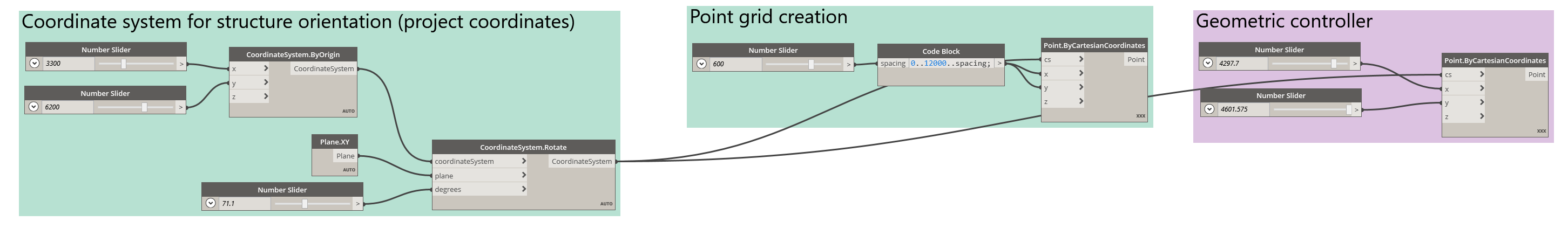
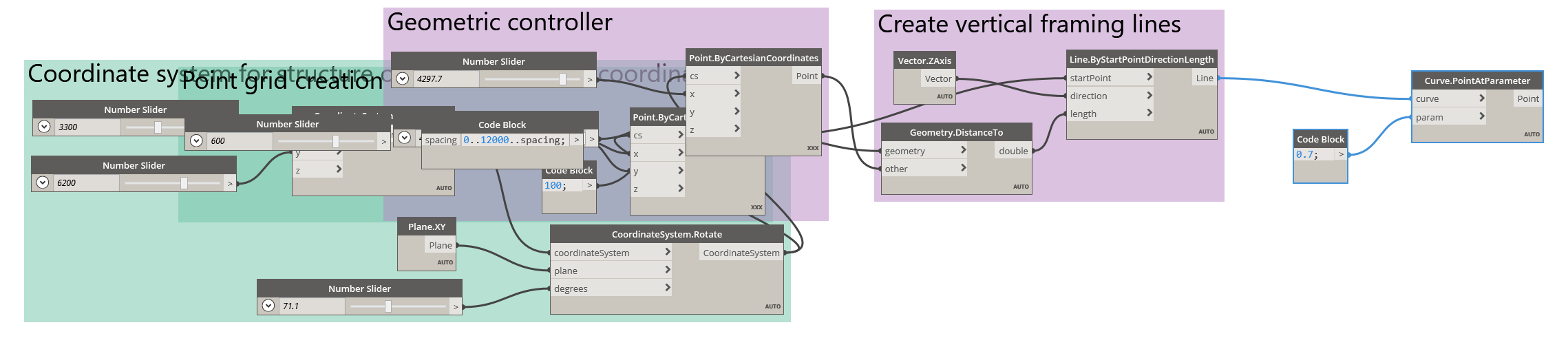
Continuing from the previous step, place a Point.ByCartesianCoordinates node. Add two sliders and connect them to the x and y inputs, adjusting each slider's Max so you can move the point near the middle of your point grid. For the cs input, connect the CoordinateSystem.Rotate from Step 1.2 so the controller shares the same coordinate space.
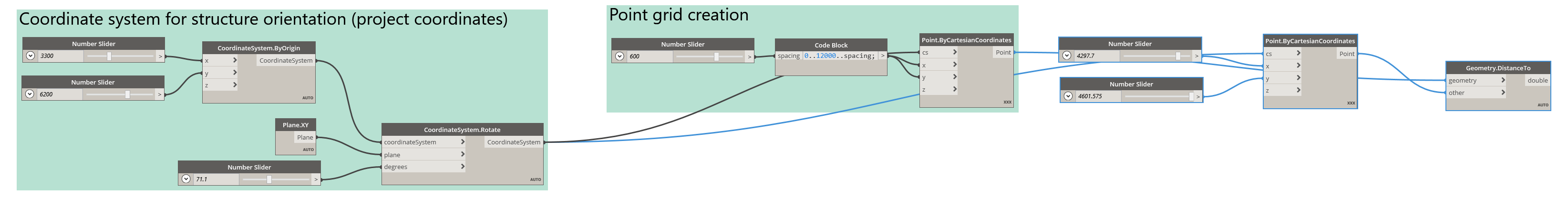 A controller point you can move around the grid.
Group these nodes and add a meaningful title.
Objective 2.2: Create the framing lines
Now create the framing lines, using the distance between the controller point and each grid point to drive each line's length.
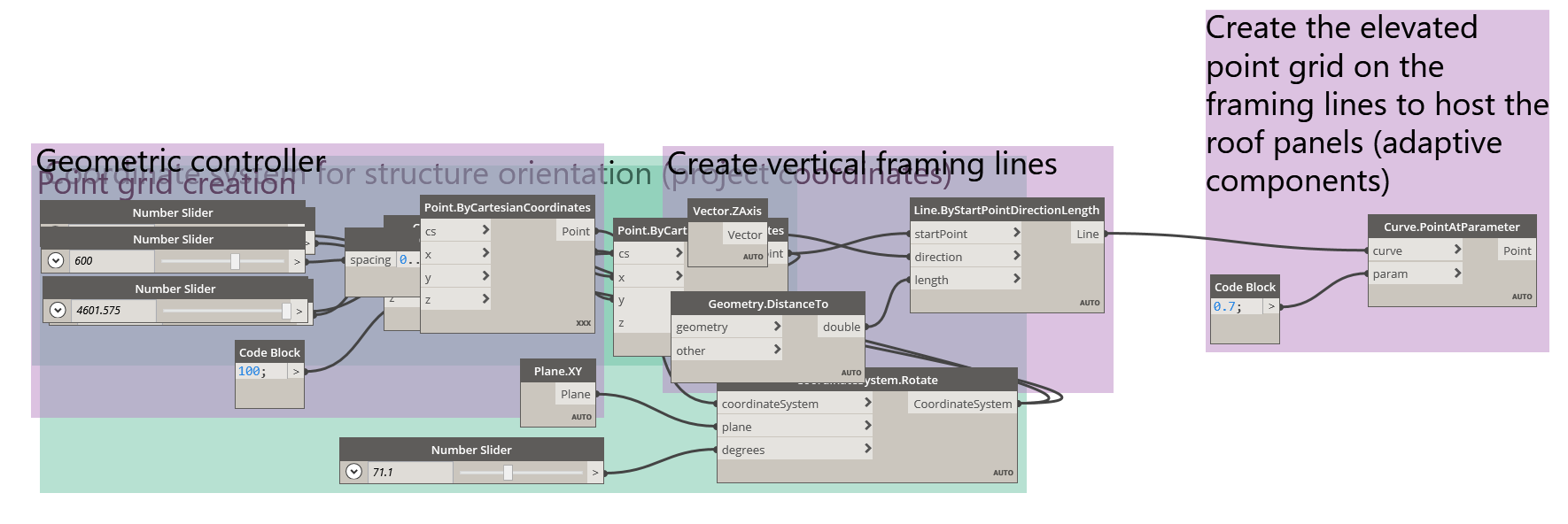
Place a Geometry.DistanceTo node. Connect the Point.ByCartesianCoordinates point grid from Step 1.3 into the geometry input, and the new controller point into the other input. This returns a list of doubles (decimal numbers) — one distance per grid point — which will define the length of each line.
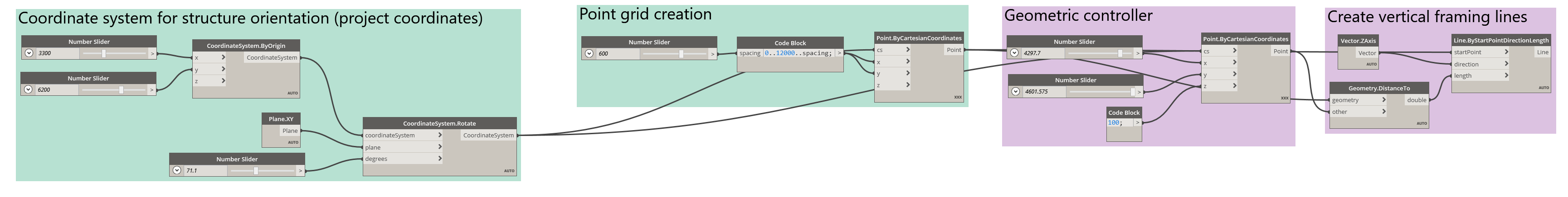
To create the lines, use the Line.ByStartPointDirectionLength node:
- startPoint — the Point.ByCartesianCoordinates point grid from Step 1.3, so the lines depend on the grid.
- direction — a Vector.ZAxis, so the lines rise vertically.
- length — the output of Geometry.DistanceTo.
Adding a value to the z input of the controller point ensures every line has at least that minimum height.
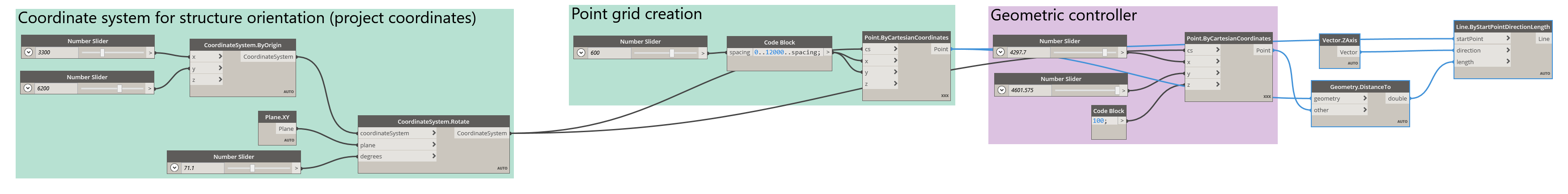 Each line's length is driven by its distance to the controller point.
A dynamic array of lines is generated, the length of each determined by the proximity of the controller point. Because each length depends on each grid point, the list structure is preserved, so every length maps effortlessly to its line. Group the nodes when you're done.
Objective 2.3: Place points along each line
Finally, place points dynamically along each framing line — these will host the adaptive components in Revit.
Place the Curve.PointAtParameter node. Into its curve input, connect the Line.ByStartPointDirectionLength node. For the parameter input, supply a double between 0.0 and 1.0.
Parameter space. A curve's parameter is essentially a percentage of its length: 0.0 is the start, 1.0 is the end, and 0.5 is the midpoint — whatever the curve's actual length. Evaluating every line at the same parameter places a point at the same proportional height on each, regardless of how long it is.
 A point placed at the same parameter on every line.
Group these nodes to complete this part of the exercise.
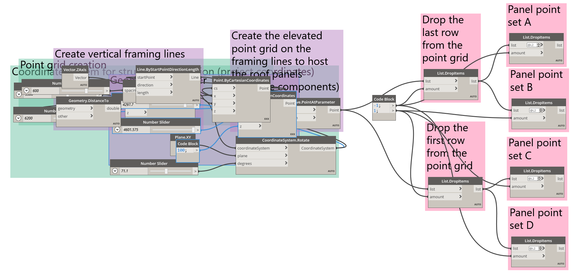 The elevated points form a new grid, ready for the list work in Step 3.